Herbalist Dr MziziMkavu
JF-Expert Member
- Feb 3, 2009
- 42,299
- 33,082
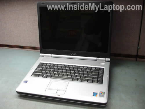
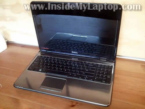
The following disassembly guide will explain how to take apart a Sony Vaio PCG-K series notebooks. I created this guide while taking apart a Sony Vaio PCG-K25 notebook but I think you can use the same disassembly steps for all notebooks in PCG-K line.
The main reason to open up the laptop was replacing broken power jack. Proceed disassembly on your own risk.
Update: I just created a new guide for Sony Vaio PCG-K series laptops. It explains how toremove and replace LCD screen with inverter board.
Before you start laptop disassembly, unplug the AC adapter and remove the battery.
Are you looking for spare parts for your Sony Vaio PCG-K series notebook? Search here.
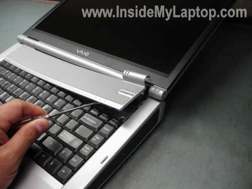
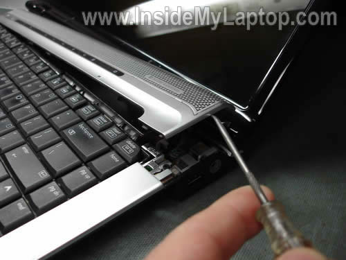
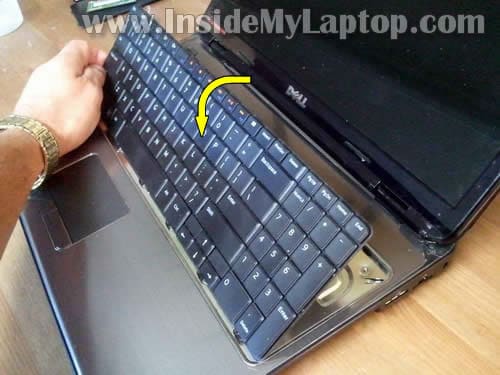
STEP 1
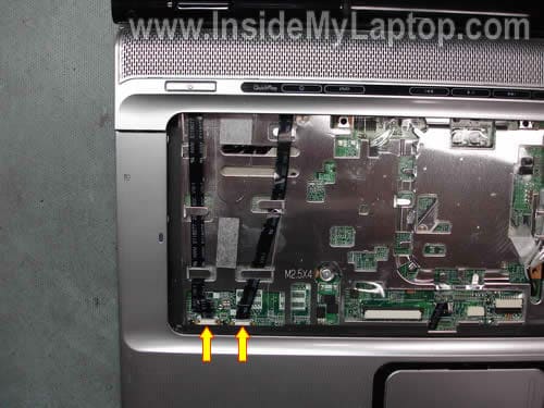
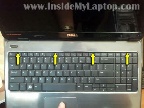
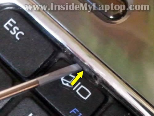
Carefully remove the keyboard bezel using a small flathead screwdriver. Remove it slowly, there is a flat ribbon cable connecting the power button board with the motherboard.
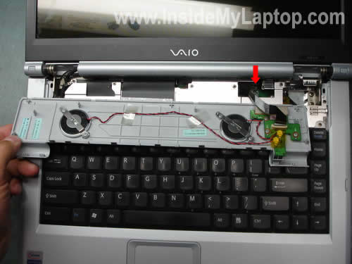
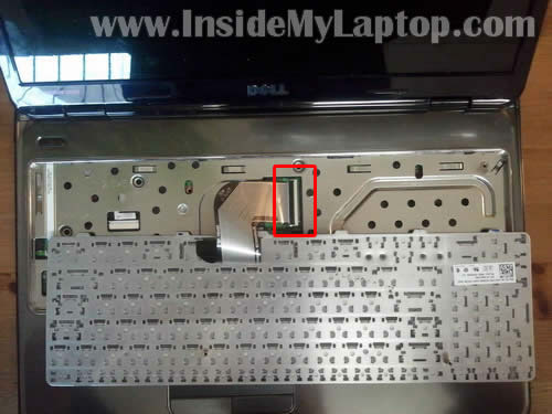
STEP 2
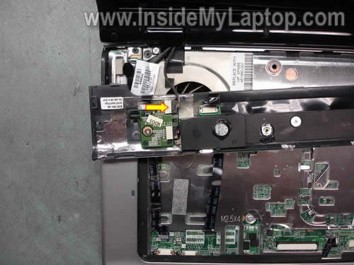
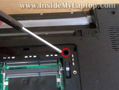
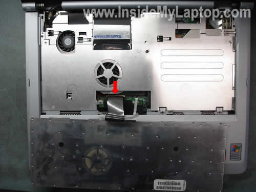
Trun the keyboard bezel upside down. The red arrow pointing to the connecto on the motherboard.
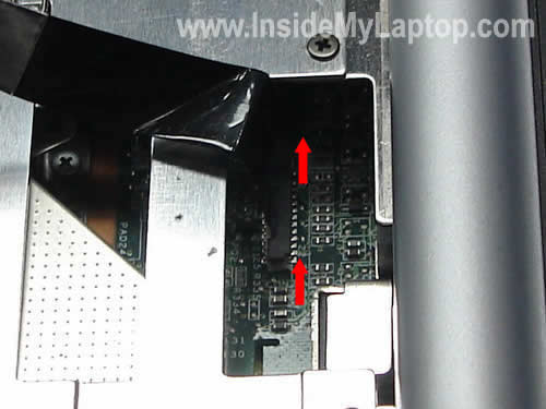
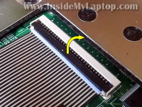
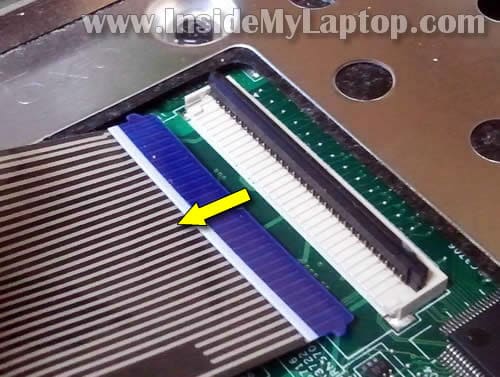
STEP 3
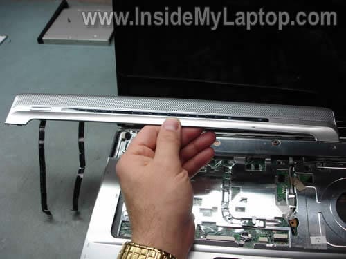
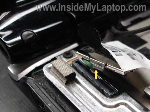
Unlock the connector by lifting up the top side of the connector 1-2 millimeters. Be very very careful. If you break any connector on the motherboard you are screwed big time. After the connector is unlocked, you can pull the cable and remove the keyboard bezel.
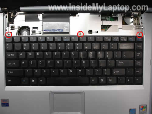
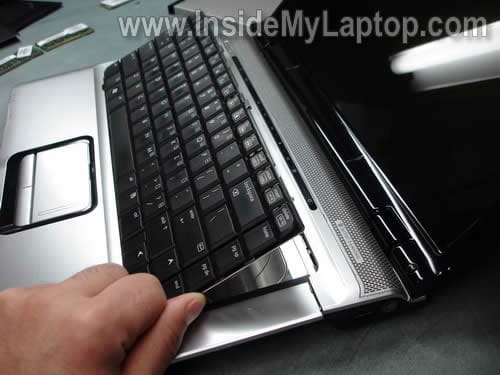
STEP 4
Remove three screws from the keyboard.
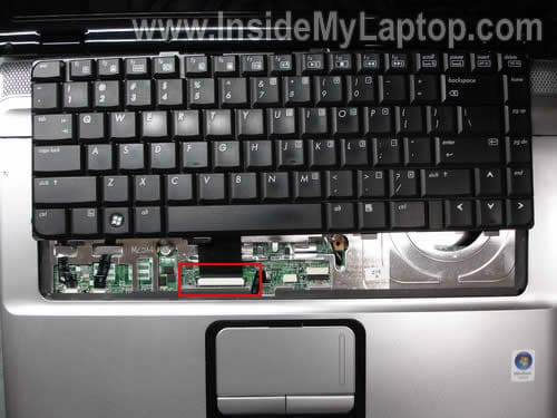
STEP 5
Lift up the keyboard and place it upside down on the palm rest. Unlock the keyboard cable connector on the motherboard. Disconnect the keyboard cable and remove the keyboard.
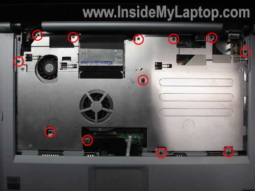
STEP 6
Remove all screws securing the metal cover.
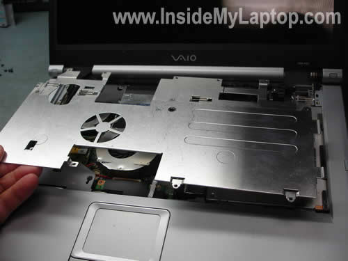
STEP 7
Remove the cover.
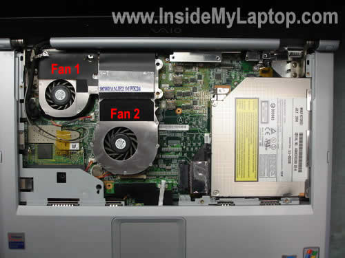
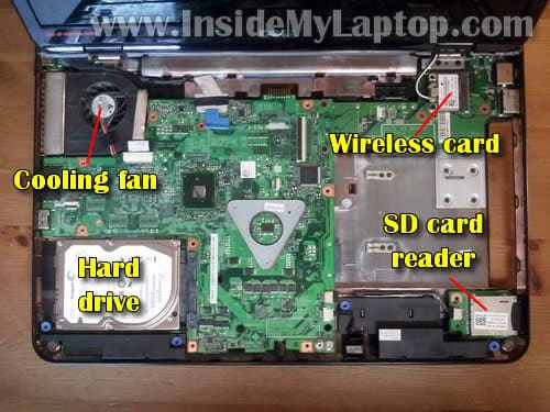
STEP 8
After the cover has been removed, you can access and clean both cooling fans. You can clean fans with compressed air.
STEP 9
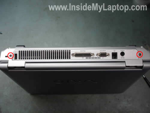
Remove two screws securing display hinges to the back side of the base.
STEP 10
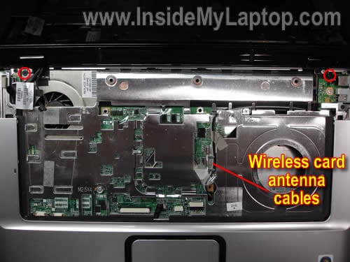
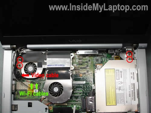
Remove four screws securing display hinges. Unplug the video cable from the motherboard. Unplug both wireless card antenna cables from the wireless card.
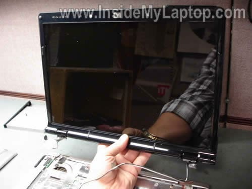
STEP 11
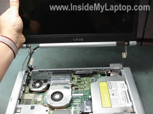
Lift up and remove notebook display panel.
STEP 12
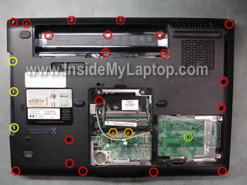
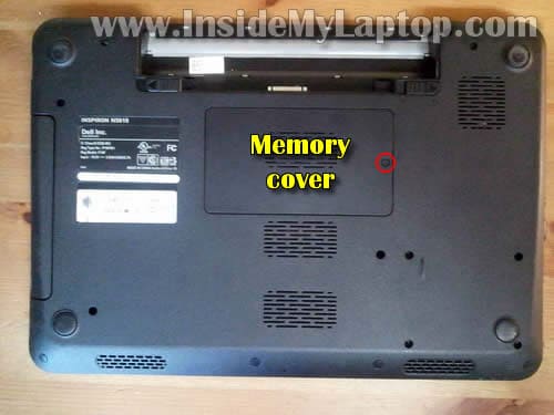
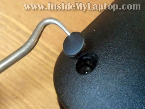
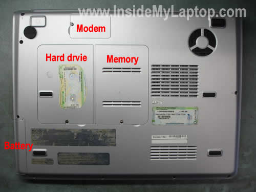
Remove hard drive cover, memory cover and modem cover from the bottom of the notebook. Each cover is secured by one screw.

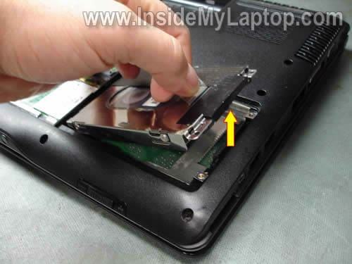
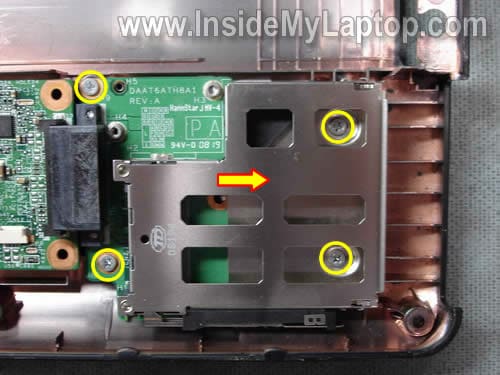
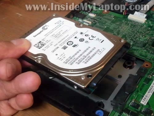
STEP 13
Heres how you can remove the hard drive. Remove four screws securing the hard drive caddy to the base assembly. Slide the hard drive down to disconnect it from the motherboard. Lift up and remove the hard drive.
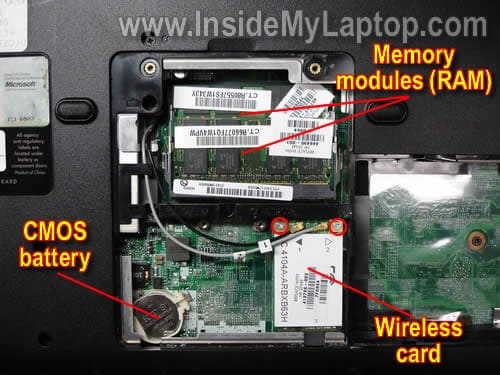
STEP 14
Removing memory modules (if needed). Carefully spread latches on both sides of the memory slot. The memory module will pop up at 30 degree angle. Pull the memory module from the slot by the edges.
Removing modem card (if needed). Remove two screws securing the modem card. Lift up the modem card to disconnect it from the motherboard and unplug cable from the side.
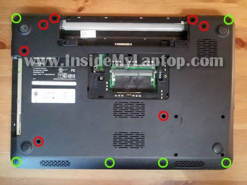
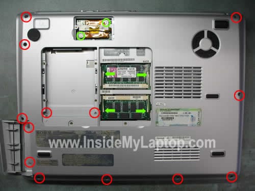
Remove all screws from the bottom of the notebook
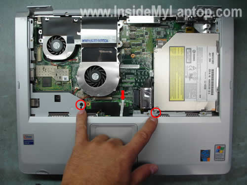
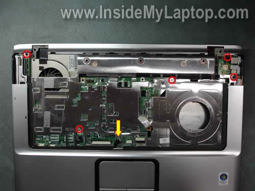
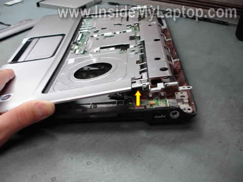
STEP 15
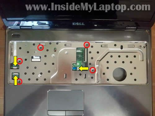
Remove two screws securing the top cover assembly. Disconnect the touch pad cable connector on the motherboard and unplug the cable.
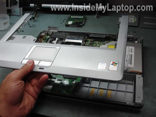
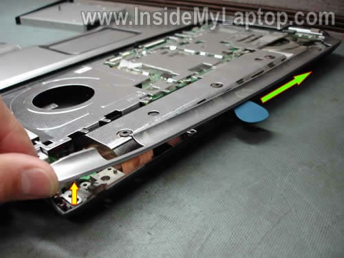
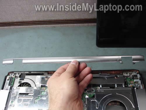
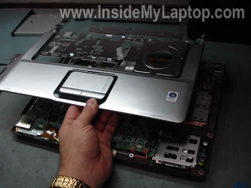
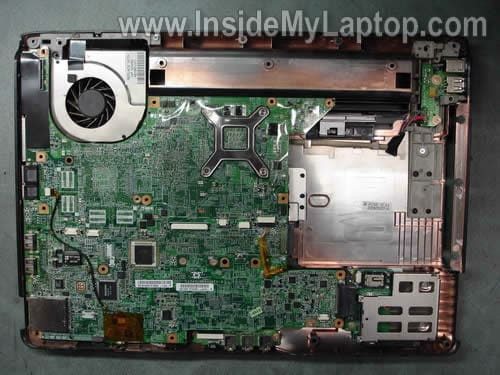
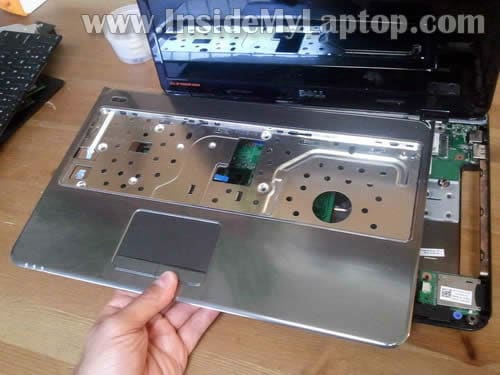
STEP 16
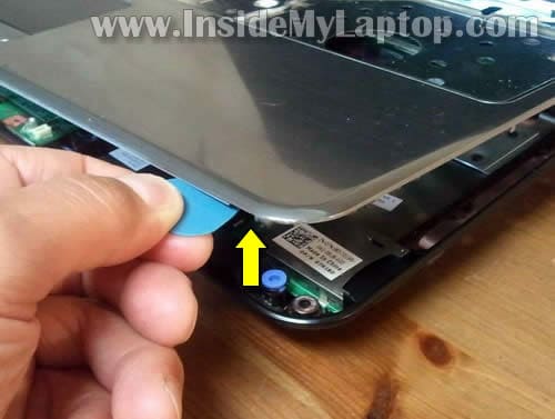
Lift up and remove the top cover assembly.
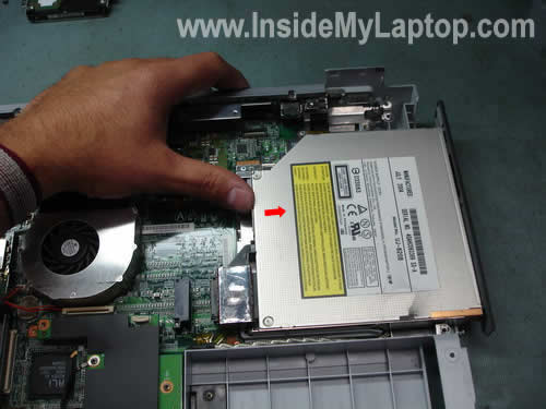
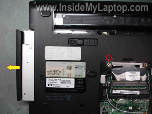
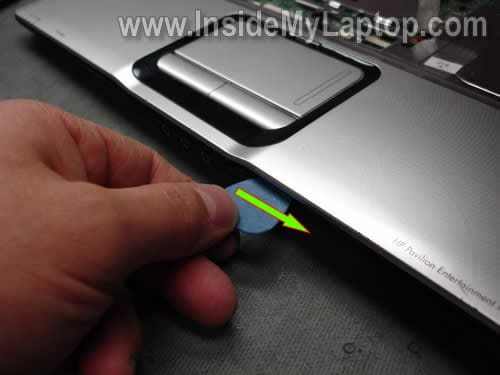
STEP 17
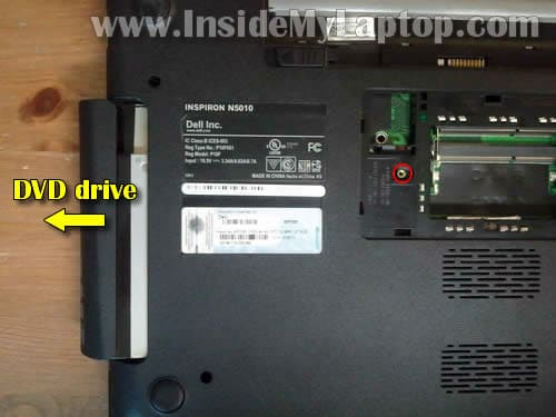
Push the CD/DVD drive to the right side with your thumb. Remove the CD/DVD drive.
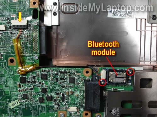
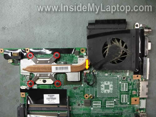
STEP 18
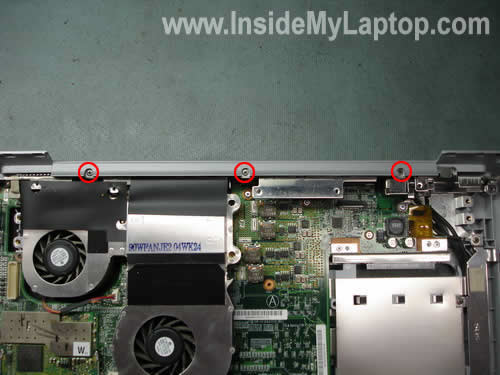
Remove three screws securing the plastic cover.

STEP 19
Remove the cover.
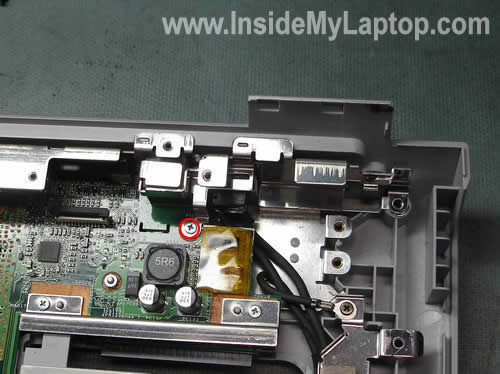
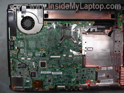
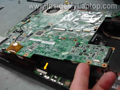
STEP 20
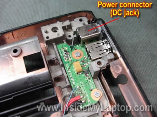
The power jack is hidden under the metal bracket. Remove one screw securing the bracket.
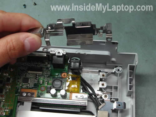
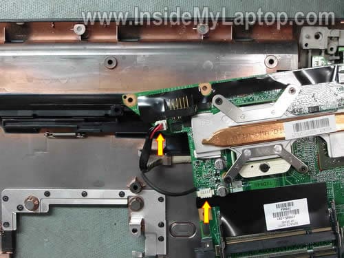
STEP 21
Lift up the bracket. Now you can access the power jack.
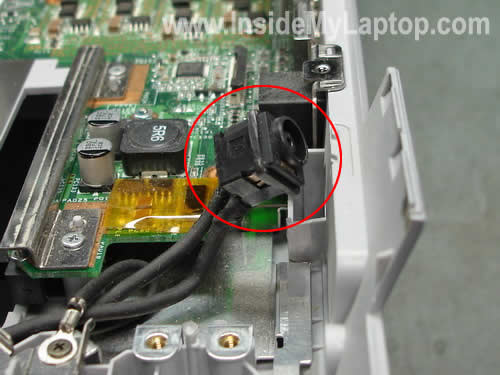
Release the power jack. Now you can remove the old power jack (unsolder from the harness) and replace it with a new power jack.
How to disassemble Sony Vaio PCG-K series notebooks. Step-by-step instructions. >> Inside my laptop